Project 08 · Case study
Process systems design
HTL Gas to Dimethyl Carbonate
A full Aspen Plus conceptual process design that upgrades a CO2-rich HTL off-gas into DMC through gas clean-up, syngas generation, methanol synthesis, azeotropic separation and heat integration.
Feed
HTL gas
61.14 mol% CO2
Product target
99.5 wt% DMC
3,950.4 kg/h product stream
Process architecture
One route from off-gas to a valuable carbonate
The process separates the HTL gas into useful carbon and fuel-rich streams, builds the required reactants, then synthesizes and purifies DMC.
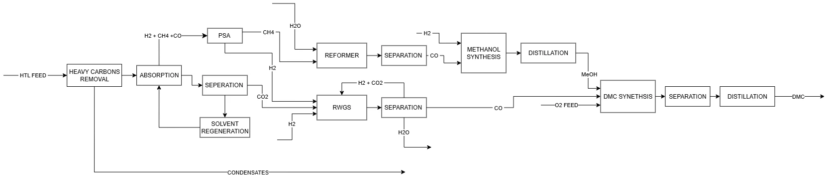
Recover carbon
Condensables are removed first, followed by physical CO2 absorption and solvent regeneration.
Build reactants
SMR and RWGS generate syngas and CO while a high-pressure loop produces purified methanol.
Make and separate DMC
Oxidative carbonylation is followed by dehydration, pressure-swing distillation and decanting.
Integrated flowsheet
A complete Aspen Plus plant model
The final flowsheet links gas clean-up, reforming, RWGS, methanol, DMC synthesis, recycle loops, product separation and heat recovery.
The model was built as one connected process so upstream choices propagate into downstream feed quality, recycle loads, utility demand and product economics.

Gas clean-up
Capture CO2 without throwing away the feed
A cold-methanol physical absorption route was selected for the high-pressure, CO2-rich HTL gas, followed by staged solvent regeneration.
Balances condensable removal against CO2 losses before absorption.
Cold methanol is contacted counter-currently with the gas feed.
Low solvent temperature increases physical CO2 absorption capacity.
Selected from the CO2 and methanol purity sensitivity study.
Reactant preparation
Sensitivity-driven syngas and methanol design
Reactor conditions and make-up flows were selected by tracking conversion, composition, pressure integration and downstream separation requirements.
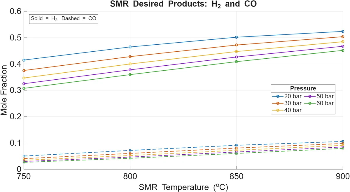
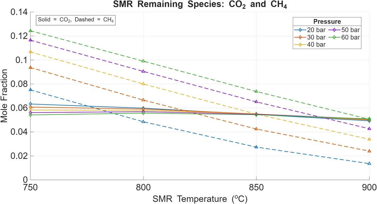
Steam methane reforming
850 °C · 20 bar
S/C = 3.0 with 73.42 kmol/h external steam, followed by cooling and water removal at 30 °C.
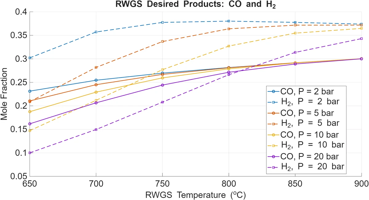
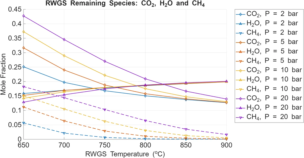
Reverse water-gas shift
900 °C · 2 bar
High temperature and low pressure favour CO, with staged water knock-out and a recycle-purge loop.
Methanol synthesis
High-pressure reaction, recycle and purification
The selected reactor condition was 250 °C and 80 bar with 150 kmol/h fresh hydrogen. The final RadFrac design used 15 stages, feed on stage 9, reflux ratio 1.0 and D:F = 0.995.
99.307 wt% methanol · 3,522.55 kg/h methanol component flow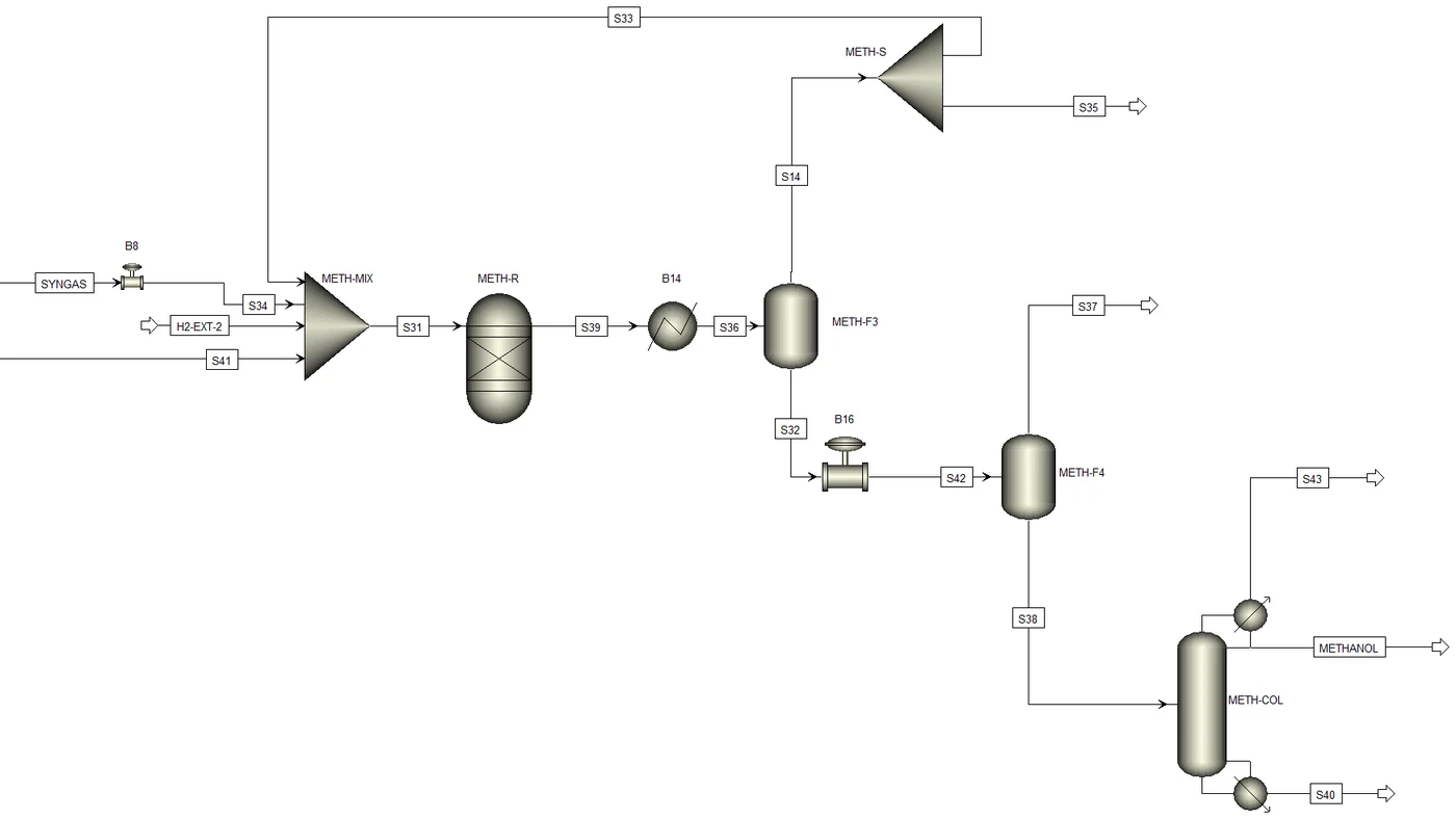
DMC synthesis and separation
Design around the azeotropes
The EniChem oxidative-carbonylation route was modelled at 120 °C and 27 atm using a CuCl catalyst representation and a 20% methanol conversion per pass.
NRTL was applied locally to the strongly non-ideal DMC/methanol/water system, with Henry treatment for dissolved light gases. The separation train was then built from the residue-curve topology rather than from trial-and-error column placement.
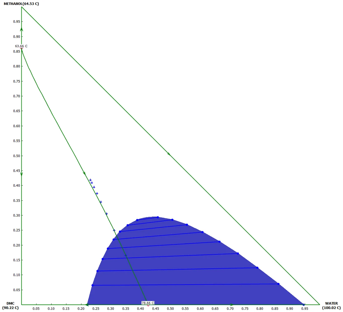
Atmospheric distillation removes water and leaves a dry methanol/DMC stream.
The methanol/DMC azeotrope shifts from about 0.86 xMeOH at 1 atm to about 0.96 at 10 bar.
The heterogeneous DMC/water split is used to cross the liquid-liquid boundary.
The final sequence targets a 99.5 wt% DMC product.
Heat integration
Recover heat at both temperature extremes
High-temperature reactor effluent is recuperated internally, while deep solvent cooling is paired with useful district-heating recovery.
Hot reformer effluent preheats the cold reactor feed.
High-grade RWGS heat is returned to the incoming feed.
A propylene cycle supplies the -50 °C absorption duty.
Condenser heat raises water from 40 °C to 85.7 °C.
Utility economics
The model also exposed the next optimization target
Utility OPEX remained slightly above estimated DMC revenue under the stated cost and price assumptions, making deeper heat integration and separation-duty reduction the clearest next design step.
Engineering outcome
A complete flowsheet with a quantified improvement path
The project connects feed conditioning, carbon capture, reaction, recycle, difficult azeotropic separation, heat recovery and operating economics in one process model.
More importantly, it makes the remaining weakness measurable: the pressure-swing separation train dominates the heat demand, so further integration can be targeted where it matters most.